

Engineers use computer-assisted design (CAD) software to draw models and build manufacturable blueprints. A CAD drawing gets passed from the designer to others in the fabrication and assembly departments. Everyone in the manufacturing process needs to understand the part’s constraints and tolerances clearly.
Engineers and designers learn another language: GD&T. Geometric dimensioning and tolerancing (GD&T) adds strictly defined symbols to CAD models, so everyone understands the dimensional requirements of a part—without the need for lengthy notes on every feature.
Why Designers Use GD&T Symbols
GD&T symbols express tolerances for the part’s form, fit and function. You can have looser tolerances when tolerances are better defined. Using common geometric dimensioning and tolerancing symbols can allow for more than 50% greater tolerance zones than linear or coordinate dimensioning.
Designers use geometric tolerance symbols to communicate with other participants in the manufacturing process. Scrap or reject parts cut into profit and make a project take more time. If parts don’t fit together in assembly, they must be reworked. Geometric dimensioning ensures parts will fit with the final product. GD&T symbols on drawings accurately show dimensions to eliminate confusion and costly rework.
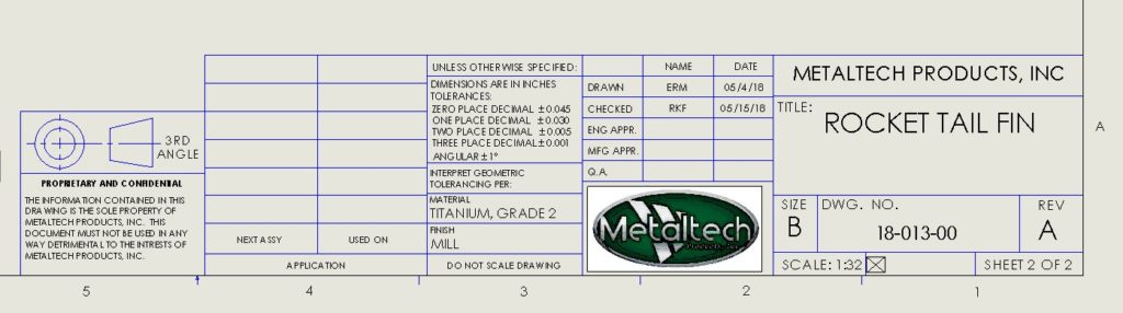
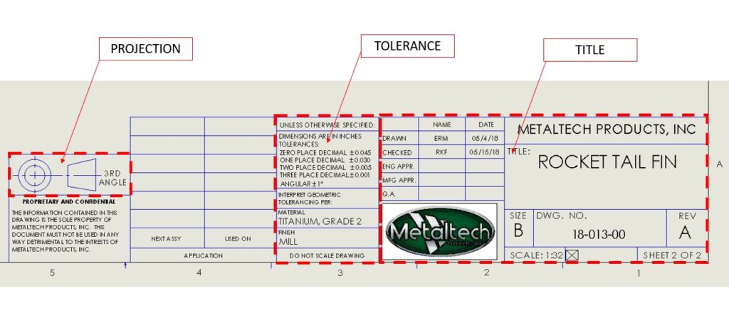
Parts of a Machining Blueprint
Machining blueprints include the blueprint title block, general tolerance block, projection types and types of feature tolerances.
- Title blocks contain high-level information like the part name, company name, drawing number, material and scale.
- Tolerance blocks display the general tolerances. These dimensions are for tolerances not further identified in the drawing.
- Projections show the part from varying angles. One part may include several drawings at different projections.
- Types of tolerances can be shown with GD&T symbols. Part designers choose from a variety of tolerance types to best reflect the part’s dimensions.
5 Types of GD&T Symbols
The American Society of Mechanical Engineers (ASME) publishes authoritative geometric dimensioning and tolerancing standards. These standards define the symbols, rules and best practices for using and interpreting GD&T. The latest edition is ASME’s Y14.5 – 2018.
According to the ASME, the five categories of GD&T symbols are:
- Form controls
- Profile controls
- Orientation controls
- Location controls
- Runout controls
GD&T Form Controls
Form controls define the final shape of the part. These controls limit deviation from tolerance on custom metal components.
Straightness
Straightness is a 2D tolerance that applies to both flat features and cylinder surfaces. Using straightness as a dimensional tolerance ensures that the part is uniform across surfaces. As a symbol, straightness is represented by a straight horizontal line.
- Line element straightness controls the form of a line on the surface or part feature.
- Axis straightness controls how much curve is tolerated in the part’s axis.
Flatness
The GD&T symbol for flatness looks like a parallelogram, tilted to the right. Flatness references how flat the face of the part or feature is. It’s the difference between the highest and lowest points on the surface. A flatness tolerance refers to two lines that are parallel to the surface. These parallel lines determine the zone where the surface must reside.
Circularity
Circularity, also known as roundness, is like straightness—if straightness was bent into a circle. When you create a circularity tolerance, you define how close the circumference should be to a perfect circle. Roundness is always less than the part’s diameter.
Circularity helps keep the feature from being too square, oblong or round. On a plane perpendicular to the part, two circles define the range where points must fall. All points have to fall between these two circles.
The circularity symbol is a circle.
Cylindricity
Similar to how circulatory is like straightness, cylindricity is much like flatness—only bent. Cylindricity combines controls for straightness and roundness, taking a 3D measurement along the entire length of the part.
The cylindricity symbol is a circle with two lines.
GD&T Profile Controls
Profile controls determine the 3D tolerance zone around the part’s features. Line and surface profiles call out the tolerance limits for curves and shapes.

Line Profile
The line profile symbol looks like an upside-down “u,” or a half-circle. Line profile controls compare a 2D cross-section to an ideal shape or curve. Two offset curves determine each feature’s tolerance zone.
Surface Profile
Surface profile controls are complex. They typically require measurement with a coordinate-measuring machine (CMM). Surface profile controls create 3D zones around the surface that show where a feature’s surface must lie. All points on the surface must fall between two virtual 3D planes.
The GD&T symbol for surface profile looks like a protractor.
GD&T Orientation Controls
Anything referring to angles is an orientation control. These controls define varying dimensions so that fabricators produce the proper angles when it’s time to manufacture.
Angularity
Angles are a big deal for parts that line up with or connect to other parts. Angularity defines a feature’s angle indirectly with respect to the relevant datum. It’s a measurement of flatness but at an angle. The GD&T symbol representing this control is similar to a “less than” sign from basic mathematics.
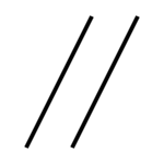
Parallelism
What other symbol would represent parallelism but two parallel lines? When you see this geometric dimensioning symbol on a drawing, it defines a feature’s straightness at a distance. Parallelism shows what surfaces need to be imitated at a 0° angle.
- Surface parallelism controls the parallelism between two surfaces or two features. Of surface and axis parallelism, surface parallelism is the more common control.
- Axis parallelism controls how parallel a central axis needs to be to another feature or axis.
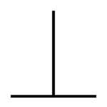
Perpendicularity
As a symbol, perpendicularity is represented by an upside-down “T.” Perpendicular angles are set to 90°. When you have a set perpendicularity, you define the flatness at 90° in regards to a specific datum. Using two perfect planes, engineers determine where the feature’s plane must be between them.
- Surface perpendicularity shows that a surface or line must be perpendicular to a datum’s surface.
- Axis perpendicularity determines how perpendicular the axis must be to a datum.
GD&T Location Controls
Location controls target linear dimensions. There are three standard location controls, though the ASME’s updated 2018 edition removed two of them.
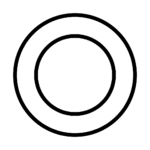
Concentricity
Concentricity is one of the tolerance controls that’s no longer in the ASME’s official guide. If you use the 2009 GD&T standards, you’ll still see concentricity as an available tolerance control. The concentricity symbol is two circles with one inside the other.
Concentricity is hard to measure and expensive to inspect, so it was removed from the 2018 standards. When defining concentricity, you control the central derived median points of a feature to maintain its circular or cylindrical aspects. Concentricity compares one feature’s axis to a datum axis. In ISO standards, concentricity is known as coaxiality.
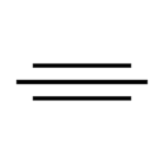
Symmetry
Symmetry is not a common tolerance, and it’s no longer a standard dimensioning tool according to the ASME’s most recent guidelines. Like concentricity, symmetry is difficult to inspect and requires a CMM to measure.
Symmetry controls the central plane around two parts of a feature, ensuring that both parts are placed an equal distance away. The midpoint between the feature’s aspects must lie within the given tolerance zone. As a symbol, symmetry is represented by three lines stacked on top of one another.

True position
True position is a beneficial and commonly used tolerance control that defines how much the position of a feature can vary from its intended position. Position uses the location of other features to set relative controls. The GD&T symbol for true position is a circle with a cross in the middle; it looks similar to a gun’s sight.
GD&T Runout Controls
Runout controls show the deviation limits of a circular feature’s ideal position. How much can a feature vary from others when the part is rotated at 360°? When one feature deviates, others may be affected. Deviation outside tolerances can render the fabricated part unusable. Essentially, runout measures the “wobble” that occurs within one part feature.
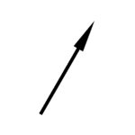
Circular Runout
Represented by an arrow symbol, circular runout is a 2D measurement of deviation in the part surface when rotated. Designers and engineers use circular runout when they need to account for several errors. When inspected, engineers rotate the fabricated part on a spindle. This test allows you to measure the variation around the axis, or the “wobble.”
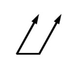
Total Runout
Total runout is like circular runout, except it measures in 3D. Circular runout measures individual cross-sections. Total runout measures entire surfaces, using multiple points on that surface. Straightness, surface profile and angularity are controlled by total runout. If you’re looking at a machining blueprint or drawing, the tolerancing symbol for runout is two arrows.
Start Your Custom Product Design
Machining blueprint symbols may be hard to read if you’re not an engineer, but our team at Metaltech is here to walk you through every part of the manufacturing process.
We design and prototype custom metal parts for your unique application. You’ll work with our experienced, degreed engineers to develop a custom metal part that meets requirements for form, fit and function.
After developing a manufacturable design, we’ll fabricate and assemble your custom parts at our facility. We’re a one-stop shop for your metal fabrication needs.
Request a quote today to start the product design process.
Image attributions:
- Straightness Symbol: Kopiersperre, Public domain, via Wikimedia Commons
- Flatness Symbol: Kopiersperre, Public domain, via Wikimedia Commons
- Circularity Symbol: Kopiersperre, Public domain, via Wikimedia Commons
- Cylindricity Symbol: Majo statt Senf, CC0, via Wikimedia Commons
- Angularity Symbol: Majo statt Senf, CC0, via Wikimedia Commons
- Parallelism Symbol: Majo statt Senf, CC0, via Wikimedia Commons
- Perpendicularity Symbol: Majo statt Senf, CC0, via Wikimedia Commons
- Concentricity Symbol: Majo statt Senf, CC0, via Wikimedia Commons
- Symmetry Symbol: Majo statt Senf, CC0, via Wikimedia Commons
- Position Symbol: Majo statt Senf, Public domain, via Wikimedia Commons
- Circular Runout Symbol: Majo statt Senf, CC0, via Wikimedia Commons