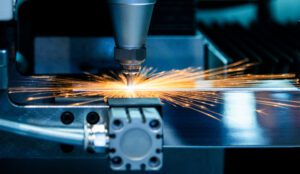
Sheet metal has a wide range of applications across multiple industries. It can be cut, formed, welded and assembled into large and small components in a myriad of shapes using complex designs.
Every fabrication project requires a solid understanding of good design principles. Material characteristics, fabrication equipment, manufacturing characteristics, and cost effectiveness are all key considerations in the design process. Different types of metal come with varying degrees of thickness and other qualities that will determine the appropriate fabrication requirements.
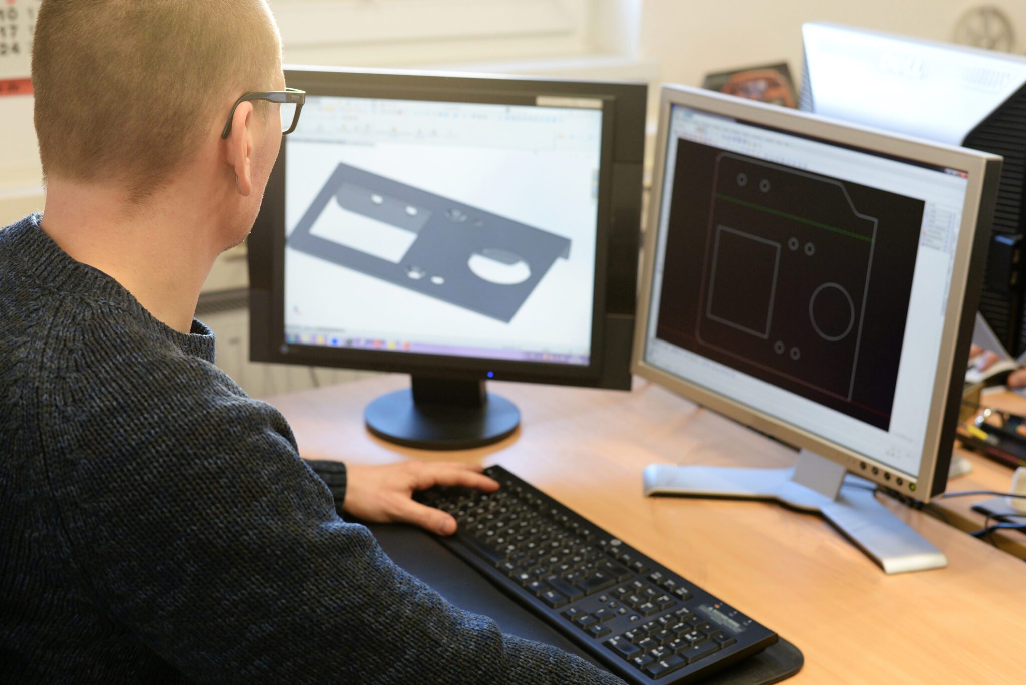
Designers and engineers create computer-based drawings and designs to guide the remaining steps in the fabrication process. At Metaltech, our engineers and engineering technicians create detailed designs for creating new products or updating existing ones. We troubleshoot problems and recommend improvements to ensure the quality of the finished product. We also create prototypes of prospective new products for testing before final production. Another specialty at Metaltech is revising overly complex design concepts into a fully functional product that is efficient and cost effective to manufacture.
Let’s take a closer look at the basic process and technologies behind advanced product design. We’ll also go over the relationship between advanced design and the subsequent steps in the metal fabrication process.
Design for Metal Fabrication
A quality design drawing ensures accurate specifications for the manufacturing process. CAD drawings must match the real-world manufacturing process, following a principle known as Design for Manufacturability or DFM. This is a step that is often overlooked when thinking about the end success portfolio of a product.
At Metaltech, our experienced design engineers and technicians collaborate with clients to ensure the most efficient and cost effective methods are used to produce a part to the customer required specifications. If the customer has limited engineeing staff, Metaltech offers a service where a customer provided product concept or sketch can serve as the platform for Metaltech’s engineering team to work with the customer’s input to produce a manufacturable design package.
Design Details
First and foremost, the design must clarify overall dimensions and product specifications. Details include material characteristics such as thickness, along with tolerances, surface flatness, bend radius, height, width and length of the component. The drawing must also specify locations and diameters of holes, weld callouts, and any special finishing requirements.
Simplification
A second primary design goal is to simplify the remaining fabrication steps for ease of manufacture. This can be achieved by removing redundant or non-essential features that don’t add value. Simplification helps to minimize costs while adhering to predetermined specifications.
Tolerances
Third, tolerance relates to the precision of the design and ensures product consistency. Requirements vary for different projects and industries. Tighter, near-zero tolerances reqiure more advanced equipment and fabricator skill while raising production costs.
Prototypes & Testing
Fourth, Metaltech uses advanced design to create prototypes for testing and enhancement. Prototype testing ensures that the final product actually works as intended before moving on to full-scale production.
What is CAD Technology (Computer-Aided Design) and How Is CAD Technology Used
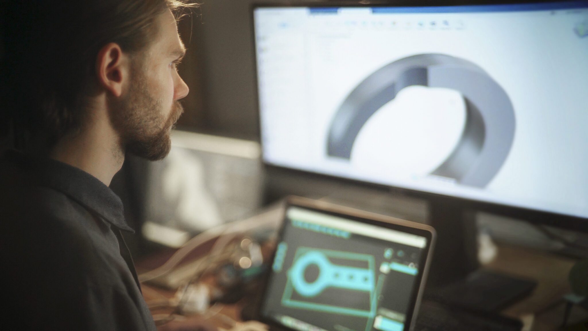
CAD (Computer-Aided Design) technology revolutionizes design creation by utilizing computer systems to generate precise 2D or 3D representations of objects, structures, or products.
It empowers designers and engineers to create, modify, and analyze designs with accurate measurements and specifications. CAD software facilitates detailed drafting, modeling, and visualization, allowing for realistic renderings, simulations, and analyses of various factors. Its collaborative features enable multiple users to work concurrently, streamlining teamwork and enhancing coordination. Overall, CAD enhances efficiency, accelerates design, and minimizes errors before manufacturing phases.
Design & Other Fabrication Processes
Design provides a roadmap for other fabrication steps such as cutting, forming and welding. Advanced CAD software ensures compliance with product specifications and reduces time to market.
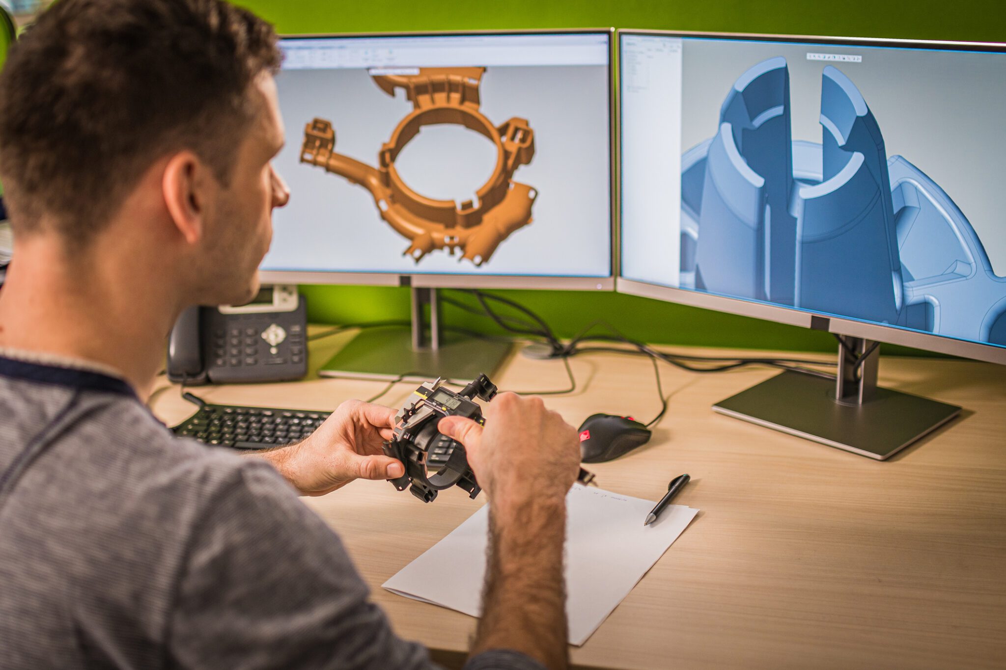
Designers and engineers utilize CAD to create accurate, detailed drawings for finished parts as well as prototypes. Drawings may be 2D or 3D, depending upon the customer’s needs.
- Designers can refine drawings an unlimited number of times before proceeding to full-scale production.
- Detailed drawings and simulations provide a realistic picture of how the product will look and function in the real world.
- Designers specify component parameters such as thickness, bend allowances, hole sizes and other geometric features.
CAD software facilitates seamless collaboration between designers, engineers and fabricators. Advanced versions combine CAD with computer-aided manufacturing, or CAM. This lets designers create toolpaths and other instructions for cutting, machining and other steps in the process.
Materials & Thickness
The fabrication process must be customized for the material selected. For example, aluminum is easier to cut than steel because of its lighter weight.
Criteria for selecting the right material include:
- Expected daily wear of the finished product
- Vulnerability to corrosion and rust
- Manufacturer specifications
- Aesthetic preferences
- Need for conductivity
- Mechanical properties
Designers should collaborate with fabricators to understand the unique qualities of different metals which will influence the manufacturing process.
The design must also specify the thickness of the metal, which typically ranges from 0.5 millimeters to 6 millimeters for most projects. The recommended thickness depends on the material and the application requirements. The advantages of thicker metals include strength and durability. A thinner metal, on the other hand, is appropriate when flexibility and a lighter weight are needed.
Cutting Guidelines
Designers must consider proper techniques when specifying holes and other cuts to a piece of sheet metal. The type of metal and the thickness of the sheet will affect the appropriate hole size. Proper distancing prevents holes from becoming deformed and maintains structural strength of the metal.
- Hole diameter must be equal to or larger than the thickness of the metal.
- The distance between two holes should be double the thickness. The ideal distance is six times the thickness.
- The appropriate distance from a hole to the edge of the sheet is equal to or larger than thickness.
- The distance from a bend to a hole should be 1.5 times sheet thickness.
Bending & Forming
The fabrication process includes bending the metal into a predetermined shape by applying pressure. Advanced press brakes use specialized hydraulic functionality to shape a cut metal sheet into a precise feature.
CAD designs tell fabricators exactly where the bend must go. All drawings and designs must accurately reflect real-world bending techniques and forming processes.
- All holes, tabs and other features must be a proper distance from the bend line. As noted above, the minimum distance from a bend to a hole is 1.5 times thickness. The distance from the bend line to other features is 4 times the thickness.
- Designers must avoid specifying perfect 90-degree angles. That’s because bending sheet metal produces a rounded corner with a bend radius, not a hard, perpendicular corner. The bend radius should equal half the length of the bent area.
Machining & Welding
Project designs must closely fit the capabilities of available welding equipment by following the principles of DFM or Design for Manufacturability. Here are a few criteria to keep in mind:
- Many welding torches cannot reach through too small an opening.
- The temperature of the welding torch must be appropriate for the selected material.
- Materials that are too thin will become deformed in the welding process.
- A successful weld typically requires a minimum thickness of 0.04 inches.
- A general rule is for the weld size to equal the thickness of the material being welded.
Finishing
Finishing is typically the last step in the fabrication process before final assembly of individual components. The correct finish depends upon the manufacturer’s goals such as protecting against corrosion or enhancing aesthetics.
Common finishes include:
- Anodizing
- Brushing
- Polishing
- Tumbling
- Bead blasting
- Powder coating
- Plating
- Passivation
- Chrome coating
Finishes can also be categorized as either protective or aesthetic.
- Protective finishes include galvanized or anodized metals, which already have a protective layer. Galvanized steel, for instance, offers durability, strength and oxidation resistance. Other options include chemical conversion treatments or zinc coatings to protect the surface and maintain structural soundness.
- Aesthetic finishes, such as powder coating, give the metal an attractive appearance. Silk screening can be used to add images such as logos, while a chromate conversion finish gives the metal conductive properties.
Get a Quote for Custom Metal Fabrication
From initial concept through finished component, Metaltech collaborates with clients to transform ideas into quality metal products. We will create a workable blueprint or 3D model or prototype based on client specifications. We also perform testing and improvement to ensure the highest quality.
Advanced design is just one of the fabrication services we offer, from cutting, bending, and welding to coating and final assembly. We do large scale production jobs as well as smaller production projects. In addition, we can scale the work to fit the needs of individual clients.
You can complete our online form to request a quote for your project. If you have a question, feel free to give us a call at 417-426-5577 or contact us online at any time.